
Instant-Download vs. Cloud-Based Software: Pros and Cons
Remember when “installing software” meant unwrapping a shiny CD, popping it into the drive, and hoping it didn’t scratch halfway through setup? Yeah. That era’s gone. Now, you can download...

ViaCAD Pro places the full power of 3D designing right at your fingertips. ViaCAD Pro’s precision solid modeling and drafting toolsets make it perfect for those who do CAD design as part of their profession. The addition of mesh-based modeling coupled with subdivision technology makes creating 3D conceptual drawings a snap. It also contains 2D switching, so you can toggle back and forth between 2D and 3D views as needed.
|
 |
ViaCAD Pro software plays nice with others. ViaCAD Pro is compatible with AutoCAD® with up-to-date DWG import and export capabilities. So your team will be able to work together without forcing everyone to be on the same brand of CAD software.
ViaCAD Pro is also compatible with over a dozen popular CAD and Graphics formats, so you’ll be able to deliver files that can be opened and edited by users of other popular design software.
Get professional quality CAD design output without pulling your hair out. Our software includes a wide selection of tools so that the right tool for the task is just a mouse click away. ViaCAD Pro has 3D mesh modeling capability with subdivision technology to go from coarse to smooth surfaces. You (and your customers) will be blown away the photorealistic rendering of your finished designs.
Drawing precisely is easy with ViaCAD! We have designed it to be user friendly and intuitive to work with.
The LogiCursor™ anticipates your next action and guides your cursor to potential point selections in the drawing.
The Gripper adds drag and drop capabilities to make editing designs easy breezy.
Customizable Grids add another level of ease by providing precision drag and drop in rectangular, polar (circular), and isometric layouts.
ViaCAD Pro is also a robust design documentation tool with over 20 customizable dimension styles, including industry dimension formats.
Other great features to help you document and annotate your projects include:
ViaCAD Pro includes all the professional level architectural tools you and your team need to draft, print, and collaborate on projects together.
ViaCAD Pro includes tools to speed up your woodworking projects. You can quickly create otherwise tedious joints such as Dado joints and miter joints.
ViaCAD provides powerful solid modeling technology found in many higher-end products. Additionally, ViaCAD Pro delivers surface modeling tools to expand design capabilities.
Checks for print viability, displaying warnings or errors to the user.
Facet normals define the inside and outside areas of a part. If facet normals are pointing the wrong way, the 3D printer may have problems creating the part. This will check for problems and we have several commands that can help you fix it.
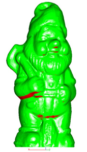
This will help you visually inspect modeling areas that may require structural support for 3D printing. Meshes, surfaces, and solids facets normals are compared to the work plane direction. Angles that are less or equal to 45 degrees are highlighted as red.
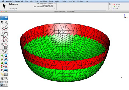
This tool provides a means to visually inspect modeling areas that may be too thin for 3D printing. Meshes, surfaces, and solids facets are examined using ray intersections.
This interface will help you to slice models given a direction and thickness. The dialog box allows for animation through the slices and single-stepping. Use to verify that a part has closed, non-overlapping sections, a requirement for 3D printing.
The Auto Position tool translates the model to the positive x, y coordinate system at z=0.
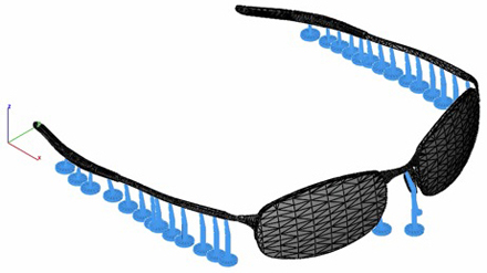
Manually adds geometry to support material as it is created by the 3D printer. Support structures controls, include Attach Radius, Midpoint Radius, Base Radius, Base Thickness, and Drag base and midpoints to modify structure location.
Toggles the boundary of the default 3D Printer. The volume is defined within the Printer Definitions dialog box.
Sets key parameters of the 3D printer, including length, width, and height of the volume accessible by the printer. The parameters in the Printer Definitions dialog box are used for commands such as 3D Print Check and Auto Position.
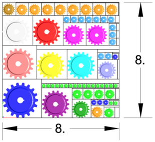
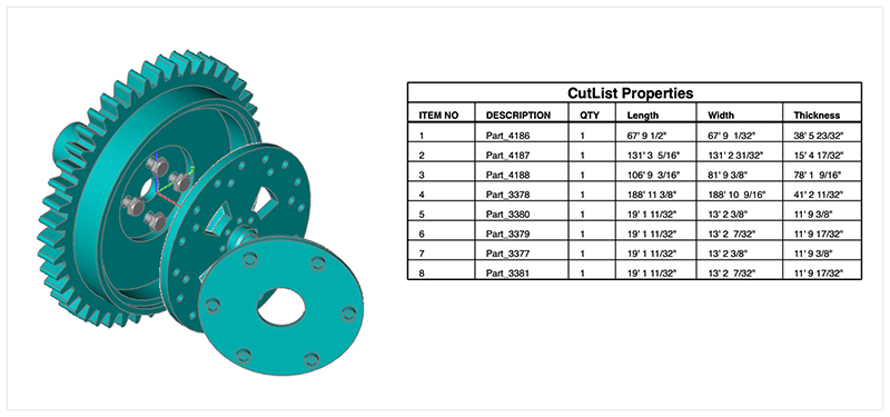
The Bill of Material Create BOM feature has a new option to support fraction measurements. To use this feature, select the Attributes and BOM dialog box from the Tools menu. Select your objects and associated a data set such as CutList properties. Apply to selected. Now select the Create BOM option to create a table. In the BOM Settings dialog box, select the Decimals pull down option. And then Select Fractions to display measurements as factions of feet and inches.
PBR, or physically based rendering, is a method of rendering computer graphics that aims to accurately represent the way that light interacts with different materials in the real world. In PBR rendering, the appearance of a material is defined by a set of parameters that describe its physical properties, such as its roughness, reflectivity, and transparency. These parameters are used to calculate the way that light reflects off the surface of the material, taking into account the angle of the light source and the surface normal, as well as the surface's roughness and other properties.
One of the key benefits of PBR rendering is that it allows for more realistic and consistent results, as it is based on the physical properties of real-world materials rather than arbitrary artistic choices. This makes it particularly well-suited for applications where photorealism is important, such as architectural visualization, product design, and film and game development.
Key user interface components to PBR rendering include:
• Photo Render Tool Palette
• Rendering Cameras
• Render To File
• Render Window
• Render Settings
For a quick introduction to Photo Rendering with V14 see the video below:
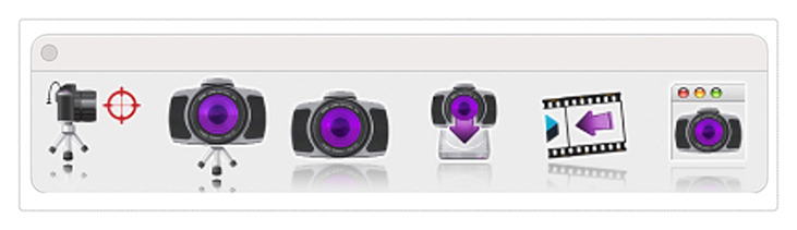
The Photo Render tool palette provides access to many of the tools used to create photo rendered images. The tool palette is access from the Tools menu bar “Photo Render” option.
The General Settings tab provides access to the following photo render settings and parameters:
| Render Presets | Presets parameters for mechanical, architectural, and jewelry scenes |
| Render Engine Type | Method of light tracing |
| Default Material | Glossy or Matte for parts with no materials assigned |
| Render Halt Time | Stop rendering after so many seconds |
| Render Halt Samples | Stop render after so many render passes |
| Render Halt Threshold | Render until pixels stop changing by this percent |
| Render Curves | Render curves as pipes |
| Render Text & Dimensions | Render Text and Dimensions as polygons |
| Ground Shadows | Create a transparent ground to catch shadows |
| Refresh Interval | Refresh the drawing screen only after so many seconds |
| Light Tracing Depth | The maximum number of light bounces |
Price: $499.99


ViaCAD Pro places the full power of 3D designing right at your fingertips. ViaCAD Pro’s precision solid modeling and drafting toolsets make it perfect for those who do CAD design as part of their profession. The addition of mesh-based modeling coupled with subdivision technology makes creating 3D conceptual drawings a snap. It also contains 2D switching, so you can toggle back and forth between 2D and 3D views as needed.
|
|
ViaCAD Pro software plays nice with others. ViaCAD Pro is compatible with AutoCAD® with up-to-date DWG import and export capabilities. So your team will be able to work together without forcing everyone to be on the same brand of CAD software.
ViaCAD Pro is also compatible with over a dozen popular CAD and Graphics formats, so you’ll be able to deliver files that can be opened and edited by users of other popular design software.
Get professional quality CAD design output without pulling your hair out. Our software includes a wide selection of tools so that the right tool for the task is just a mouse click away. ViaCAD Pro has 3D mesh modeling capability with subdivision technology to go from coarse to smooth surfaces. You (and your customers) will be blown away the photorealistic rendering of your finished designs.
Drawing precisely is easy with ViaCAD! We have designed it to be user friendly and intuitive to work with.
The LogiCursor™ anticipates your next action and guides your cursor to potential point selections in the drawing.
The Gripper adds drag and drop capabilities to make editing designs easy breezy.
Customizable Grids add another level of ease by providing precision drag and drop in rectangular, polar (circular), and isometric layouts.
ViaCAD Pro is also a robust design documentation tool with over 20 customizable dimension styles, including industry dimension formats.
Other great features to help you document and annotate your projects include:
ViaCAD Pro includes all the professional level architectural tools you and your team need to draft, print, and collaborate on projects together.
ViaCAD Pro includes tools to speed up your woodworking projects. You can quickly create otherwise tedious joints such as Dado joints and miter joints.
ViaCAD provides powerful solid modeling technology found in many higher-end products. Additionally, ViaCAD Pro delivers surface modeling tools to expand design capabilities.
Checks for print viability, displaying warnings or errors to the user.
Facet normals define the inside and outside areas of a part. If facet normals are pointing the wrong way, the 3D printer may have problems creating the part. This will check for problems and we have several commands that can help you fix it.
This will help you visually inspect modeling areas that may require structural support for 3D printing. Meshes, surfaces, and solids facets normals are compared to the work plane direction. Angles that are less or equal to 45 degrees are highlighted as red.
This tool provides a means to visually inspect modeling areas that may be too thin for 3D printing. Meshes, surfaces, and solids facets are examined using ray intersections.
This interface will help you to slice models given a direction and thickness. The dialog box allows for animation through the slices and single-stepping. Use to verify that a part has closed, non-overlapping sections, a requirement for 3D printing.
The Auto Position tool translates the model to the positive x, y coordinate system at z=0.
Manually adds geometry to support material as it is created by the 3D printer. Support structures controls, include Attach Radius, Midpoint Radius, Base Radius, Base Thickness, and Drag base and midpoints to modify structure location.
Toggles the boundary of the default 3D Printer. The volume is defined within the Printer Definitions dialog box.
Sets key parameters of the 3D printer, including length, width, and height of the volume accessible by the printer. The parameters in the Printer Definitions dialog box are used for commands such as 3D Print Check and Auto Position.
The Bill of Material Create BOM feature has a new option to support fraction measurements. To use this feature, select the Attributes and BOM dialog box from the Tools menu. Select your objects and associated a data set such as CutList properties. Apply to selected. Now select the Create BOM option to create a table. In the BOM Settings dialog box, select the Decimals pull down option. And then Select Fractions to display measurements as factions of feet and inches.
PBR, or physically based rendering, is a method of rendering computer graphics that aims to accurately represent the way that light interacts with different materials in the real world. In PBR rendering, the appearance of a material is defined by a set of parameters that describe its physical properties, such as its roughness, reflectivity, and transparency. These parameters are used to calculate the way that light reflects off the surface of the material, taking into account the angle of the light source and the surface normal, as well as the surface's roughness and other properties.
One of the key benefits of PBR rendering is that it allows for more realistic and consistent results, as it is based on the physical properties of real-world materials rather than arbitrary artistic choices. This makes it particularly well-suited for applications where photorealism is important, such as architectural visualization, product design, and film and game development.
Key user interface components to PBR rendering include:
• Photo Render Tool Palette
• Rendering Cameras
• Render To File
• Render Window
• Render Settings
For a quick introduction to Photo Rendering with V14 see the video below:
The Photo Render tool palette provides access to many of the tools used to create photo rendered images. The tool palette is access from the Tools menu bar “Photo Render” option.
The General Settings tab provides access to the following photo render settings and parameters:
| Render Presets | Presets parameters for mechanical, architectural, and jewelry scenes |
| Render Engine Type | Method of light tracing |
| Default Material | Glossy or Matte for parts with no materials assigned |
| Render Halt Time | Stop rendering after so many seconds |
| Render Halt Samples | Stop render after so many render passes |
| Render Halt Threshold | Render until pixels stop changing by this percent |
| Render Curves | Render curves as pipes |
| Render Text & Dimensions | Render Text and Dimensions as polygons |
| Ground Shadows | Create a transparent ground to catch shadows |
| Refresh Interval | Refresh the drawing screen only after so many seconds |
| Light Tracing Depth | The maximum number of light bounces |
Payment Methods We Accept
Your payment information is processed securely. We do not store credit card details nor have access to your credit card information.
Return Policy
We offer refunds to original payment method if the following are met:
Returns can be requested by logging into your account here.
We offer refunds to store credit if the following are met:
Returns can be requested by logging into your account here.
If the above requirements ARE NOT met:
The sale is considered final and cannot be returned.
Remember when “installing software” meant unwrapping a shiny CD, popping it into the drive, and hoping it didn’t scratch halfway through setup? Yeah. That era’s gone. Now, you can download...

You’re searching for a program you really need. Then, boom, you see it. A “free download.” Same program. Same name. Just… no price tag. Tempting, right? It’s one of the...

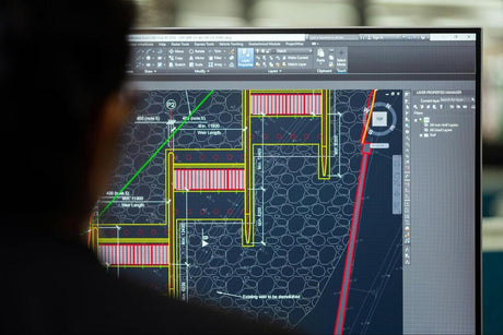
Architects once relied on pencils, rulers, and endless sheets of paper. Now, software acts as their creative sandbox. With a few clicks, they can test layouts, swap materials, or rework...

Want to splice together a tutorial, a vlog, or a short film? The best video editor on Mac lets you see your ideas come alive frame by frame. From smooth...

Whether you own a MacBook, iMac, or other macOS-compatible device, our guide will show you exactly where to find your macOS version quickly and easily.

This information is also vital to know before you purchase and install software. It’s also useful when upgrading hardware or planning to transition from one device to another, since software...

Software gifts can be just as exciting, much more affordable, and you don't have to worry about out-of-stock issues. From creative design programs to productivity tools and security software, the...
At some point in their lives, all professional CAD users had to learn how to use CAD software, and it must have felt like entering an unfamiliar workshop to them...
Microsoft
Microsoft 365 Personal - Instant Download for Windows and Mac

Kofax
Kofax Power PDF 4.0 Advanced - Instant Download for Windows
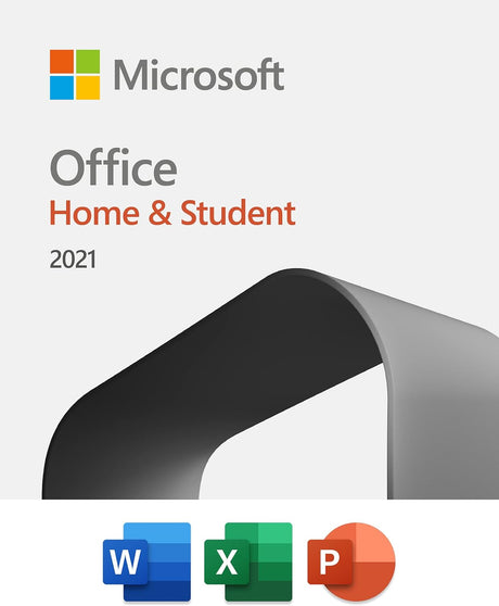
Microsoft
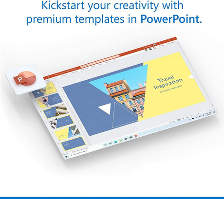
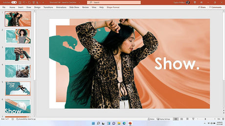
Microsoft Office Home and Student 2021 - Instant Download for Windows and Mac

Corel
Corel PaintShop Pro 2022 - Instant Download for Windows

Norton
Norton 360 Deluxe - Instant Download for Windows and Mac


Nuance
Nuance Dragon Professional 16 - Instant Download for Windows

Category
Platform
Compatible Operating Systems
License Type
Number of Computers/Users