
Instant-Download vs. Cloud-Based Software: Pros and Cons
Remember when “installing software” meant unwrapping a shiny CD, popping it into the drive, and hoping it didn’t scratch halfway through setup? Yeah. That era’s gone. Now, you can download...
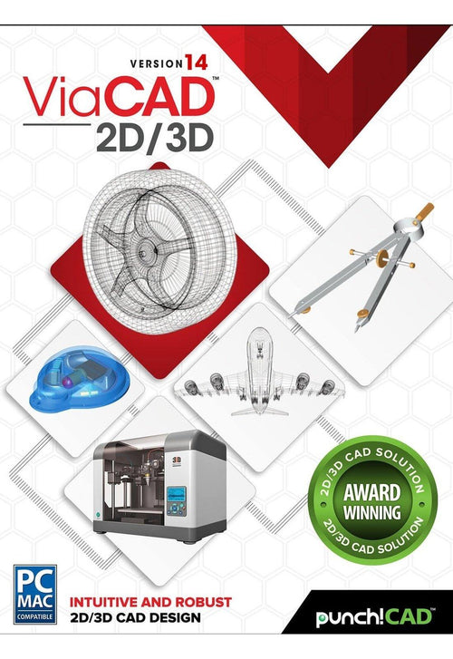
ViaCAD 2D/3D offers precision design tools for beginning to intermediate CAD software users. It allows you to create in 2D or 3D and quickly toggle between views. Our price to performance ratio blows the competition away. Amateur users will be thrilled by professional-looking results, while professionals will love how budget-friendly this version of ViaCAD is.
|
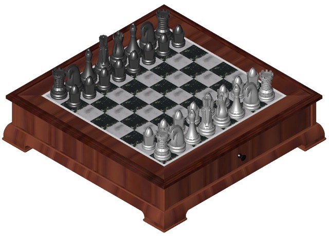 |
ViaCAD software plays nice with others. ViaCAD is compatible with AutoCAD® with up-to-date DWG import and export capabilities. So your team will be able to work together without forcing everyone to be on the same brand of CAD software.
ViaCAD is also compatible with over a dozen popular CAD and Graphics formats, so you’ll be able to deliver files that can be opened and edited by users of other popular design software.
|
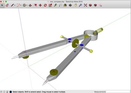 |
Make your designs come to life with our powerful 3D CAD software. Begin exploring the powerful world of 3D mesh modeling! ViaCAD provides solid modeling technology found in many higher-end products. There is behind-the-scenes programming that connects 2D and 3D, so that you can edit 2D profiles used to create 3D objects and the 3D shape will automatically update.
Drawing precisely is easy with ViaCAD! We have designed it to be user friendly and intuitive to work with.
The LogiCursor™ anticipates your next action and guides your cursor to potential point selections in the drawing.
The Gripper adds drag and drop capabilities to make editing designs easy breezy.
Customizable Grids add another level of ease by providing precision drag and drop in rectangular, polar (circular), and isometric layouts.
ViaCAD 2D/3D includes 3D printing tools to prepare and validate your designs to make them 3D printer ready.
Checks for print viability, displaying warnings or errors to the user.
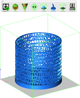
Facet normals define the inside and outside areas of a part. If facet normals are pointing the wrong way, the 3D printer may have problems creating the part. This will check for problems and we have several commands that can help you fix it.
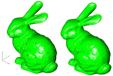
This will help you visually inspect modeling areas that may require structural support for 3D printing. Meshes, surfaces, and solids facets normals are compared to the work plane direction. Angles that are less or equal to 45 degrees are highlighted as red.
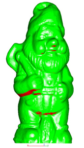
This tool provides a means to visually inspect modeling areas that may be too thin for 3D printing. Meshes, surfaces, and solids facets are examined using ray intersections.
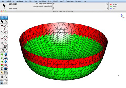
This interface will help you to slice models given a direction and thickness. The dialog box allows for animation through the slices and single-stepping. Use to verify that a part has closed, non-overlapping sections, a requirement for 3D printing.

The Auto Position tool translates the model to the positive x, y coordinate system at z=0.
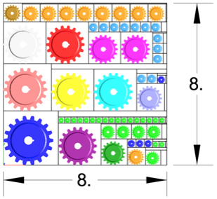
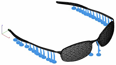
Manually adds geometry to support material as it is created by the 3D printer. Support structures controls, include Attach Radius, Midpoint Radius, Base Radius, Base Thickness, and Drag base and midpoints to modify structure location.
Toggles the boundary of the default 3D Printer. The volume is defined within the Printer Definitions dialog box.
Sets key parameters of the 3D printer, including length, width, and height of the volume accessible by the printer. The parameters in the Printer Definitions dialog box are used for commands such as 3D Print Check and Auto Position.
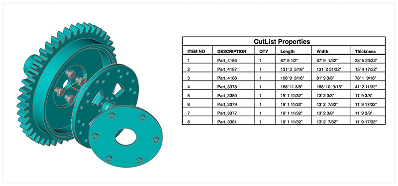
The Bill of Material Create BOM feature has a new option to support fraction measurements. To use this feature, select the Attributes and BOM dialog box from the Tools menu. Select your objects and associated a data set such as CutList properties. Apply to selected. Now select the Create BOM option to create a table. In the BOM Settings dialog box, select the Decimals pull down option. And then Select Fractions to display measurements as factions of feet and inches.
PBR, or physically based rendering, is a method of rendering computer graphics that aims to accurately represent the way that light interacts with different materials in the real world. In PBR rendering, the appearance of a material is defined by a set of parameters that describe its physical properties, such as its roughness, reflectivity, and transparency. These parameters are used to calculate the way that light reflects off the surface of the material, taking into account the angle of the light source and the surface normal, as well as the surface's roughness and other properties.
One of the key benefits of PBR rendering is that it allows for more realistic and consistent results, as it is based on the physical properties of real-world materials rather than arbitrary artistic choices. This makes it particularly well-suited for applications where photorealism is important, such as architectural visualization, product design, and film and game development.
Key user interface components to PBR rendering include:
• Photo Render Tool Palette
• Rendering Cameras
• Render To File
• Render Window
• Render Settings
For a quick introduction to Photo Rendering with V14 see the video below:
The Photo Render tool palette provides access to many of the tools used to create photo rendered images. The tool palette is access from the Tools menu bar “Photo Render” option.

The laser light adds a direct light source that emits a focused beam of light. Laser Lights are defined by a start point, end point, radius, and gain. The start point defined the laser start while the end point defines the direction of the light. The radius value defines the cylinder region of light. The gain defines the strength of the light.

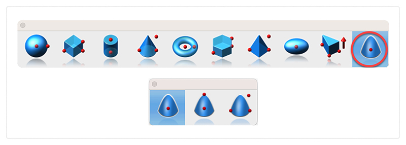
The paraboloid primitive provides a means to create a quadric surface from one-, two-, or three-point definitions. Use a paraboloid to create a reflectors/radars, automobile headlights, solar furnaces, antennas, and aerodynamic tips. The Paraboloid primitive is located in the solid primitives tool palette, last tool item. The one-point paraboloid has a base center, and three radius values. The two-point paraboloid has a base center, end. The three point has two points defining the base diagonal, and one point defining the height. Each method provides a data entry window interface to change the associated radius values.
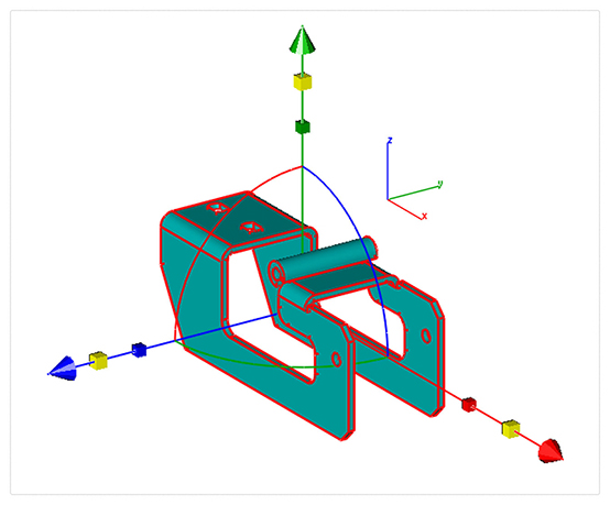
The Gripper has a new graphic widget to perform non uniform scaling via a handle. To use this feature, display the inspector and select the gripper properties tab. Then select “Enable Gripper”. The non-uniform scale graphic is the red, blue, or green box display along the associated axis. Select, hold and drag over the box to scale along that particular axis.
Red scales along x
Blue along y
And Green scales along z
You can scale curves, surfaces, or solids. Use the data entry window to scale a precise amount.
A new dimension tool was introduced to support area-based measurements. To access the Area Dimension tool tear out the dimension tool palette and select the area dimension tool icon. The area dimension works with collections of closed curves or polygons. There are two options accessed through the data entry window.
1. Leader Line Dimension
2. Text at Centroid
Select Pick Leader Line Dimension. And now select the collection of curves or polygon. Then select the arrow location and text location. Now change the area method to text at centroid. And select the polygon. The area dimension is associative to the curves originally selected. Modifying a curve will update the area dimension. The Area dimension also work with a collection of curves used in a constrained system. In this case, updating any dimension value, will update the area dimension.

The core modeling kernel was updated to support a newer version from Spatial. The new update provides greater increases in quality and robustness and improvements in modeling tasks such as booleans, blending, chamfering, sweeps, skinning, healing, and faceting functionality.
Price: $199.99
ViaCAD 2D/3D offers precision design tools for beginning to intermediate CAD software users. It allows you to create in 2D or 3D and quickly toggle between views. Our price to performance ratio blows the competition away. Amateur users will be thrilled by professional-looking results, while professionals will love how budget-friendly this version of ViaCAD is.
|
 |
ViaCAD software plays nice with others. ViaCAD is compatible with AutoCAD® with up-to-date DWG import and export capabilities. So your team will be able to work together without forcing everyone to be on the same brand of CAD software.
ViaCAD is also compatible with over a dozen popular CAD and Graphics formats, so you’ll be able to deliver files that can be opened and edited by users of other popular design software.
|
 |
Make your designs come to life with our powerful 3D CAD software. Begin exploring the powerful world of 3D mesh modeling! ViaCAD provides solid modeling technology found in many higher-end products. There is behind-the-scenes programming that connects 2D and 3D, so that you can edit 2D profiles used to create 3D objects and the 3D shape will automatically update.
Drawing precisely is easy with ViaCAD! We have designed it to be user friendly and intuitive to work with.
The LogiCursor™ anticipates your next action and guides your cursor to potential point selections in the drawing.
The Gripper adds drag and drop capabilities to make editing designs easy breezy.
Customizable Grids add another level of ease by providing precision drag and drop in rectangular, polar (circular), and isometric layouts.
ViaCAD 2D/3D includes 3D printing tools to prepare and validate your designs to make them 3D printer ready.
Checks for print viability, displaying warnings or errors to the user.

Facet normals define the inside and outside areas of a part. If facet normals are pointing the wrong way, the 3D printer may have problems creating the part. This will check for problems and we have several commands that can help you fix it.

This will help you visually inspect modeling areas that may require structural support for 3D printing. Meshes, surfaces, and solids facets normals are compared to the work plane direction. Angles that are less or equal to 45 degrees are highlighted as red.

This tool provides a means to visually inspect modeling areas that may be too thin for 3D printing. Meshes, surfaces, and solids facets are examined using ray intersections.

This interface will help you to slice models given a direction and thickness. The dialog box allows for animation through the slices and single-stepping. Use to verify that a part has closed, non-overlapping sections, a requirement for 3D printing.

The Auto Position tool translates the model to the positive x, y coordinate system at z=0.

Manually adds geometry to support material as it is created by the 3D printer. Support structures controls, include Attach Radius, Midpoint Radius, Base Radius, Base Thickness, and Drag base and midpoints to modify structure location.

Toggles the boundary of the default 3D Printer. The volume is defined within the Printer Definitions dialog box.
Sets key parameters of the 3D printer, including length, width, and height of the volume accessible by the printer. The parameters in the Printer Definitions dialog box are used for commands such as 3D Print Check and Auto Position.
The Bill of Material Create BOM feature has a new option to support fraction measurements. To use this feature, select the Attributes and BOM dialog box from the Tools menu. Select your objects and associated a data set such as CutList properties. Apply to selected. Now select the Create BOM option to create a table. In the BOM Settings dialog box, select the Decimals pull down option. And then Select Fractions to display measurements as factions of feet and inches.

PBR, or physically based rendering, is a method of rendering computer graphics that aims to accurately represent the way that light interacts with different materials in the real world. In PBR rendering, the appearance of a material is defined by a set of parameters that describe its physical properties, such as its roughness, reflectivity, and transparency. These parameters are used to calculate the way that light reflects off the surface of the material, taking into account the angle of the light source and the surface normal, as well as the surface's roughness and other properties.
One of the key benefits of PBR rendering is that it allows for more realistic and consistent results, as it is based on the physical properties of real-world materials rather than arbitrary artistic choices. This makes it particularly well-suited for applications where photorealism is important, such as architectural visualization, product design, and film and game development.
Key user interface components to PBR rendering include:
• Photo Render Tool Palette
• Rendering Cameras
• Render To File
• Render Window
• Render Settings
For a quick introduction to Photo Rendering with V14 see the video below:
The Photo Render tool palette provides access to many of the tools used to create photo rendered images. The tool palette is access from the Tools menu bar “Photo Render” option.

The laser light adds a direct light source that emits a focused beam of light. Laser Lights are defined by a start point, end point, radius, and gain. The start point defined the laser start while the end point defines the direction of the light. The radius value defines the cylinder region of light. The gain defines the strength of the light.

The paraboloid primitive provides a means to create a quadric surface from one-, two-, or three-point definitions. Use a paraboloid to create a reflectors/radars, automobile headlights, solar furnaces, antennas, and aerodynamic tips. The Paraboloid primitive is located in the solid primitives tool palette, last tool item. The one-point paraboloid has a base center, and three radius values. The two-point paraboloid has a base center, end. The three point has two points defining the base diagonal, and one point defining the height. Each method provides a data entry window interface to change the associated radius values.

The Gripper has a new graphic widget to perform non uniform scaling via a handle. To use this feature, display the inspector and select the gripper properties tab. Then select “Enable Gripper”. The non-uniform scale graphic is the red, blue, or green box display along the associated axis. Select, hold and drag over the box to scale along that particular axis.
Red scales along x
Blue along y
And Green scales along z
You can scale curves, surfaces, or solids. Use the data entry window to scale a precise amount.

A new dimension tool was introduced to support area-based measurements. To access the Area Dimension tool tear out the dimension tool palette and select the area dimension tool icon. The area dimension works with collections of closed curves or polygons. There are two options accessed through the data entry window.
1. Leader Line Dimension
2. Text at Centroid
Select Pick Leader Line Dimension. And now select the collection of curves or polygon. Then select the arrow location and text location. Now change the area method to text at centroid. And select the polygon. The area dimension is associative to the curves originally selected. Modifying a curve will update the area dimension. The Area dimension also work with a collection of curves used in a constrained system. In this case, updating any dimension value, will update the area dimension.

The core modeling kernel was updated to support a newer version from Spatial. The new update provides greater increases in quality and robustness and improvements in modeling tasks such as booleans, blending, chamfering, sweeps, skinning, healing, and faceting functionality.
Payment Methods We Accept
Your payment information is processed securely. We do not store credit card details nor have access to your credit card information.
Return Policy
We offer refunds to original payment method if the following are met:
Returns can be requested by logging into your account here.
We offer refunds to store credit if the following are met:
Returns can be requested by logging into your account here.
If the above requirements ARE NOT met:
The sale is considered final and cannot be returned.