Punch!CAD SharkCAD v14 - Instant Download for Windows (1 Device)
Choose Version
For Windows
For 1 Device
Additional devices/users availableInstant Download
Download immediately upon purchaseOne Time Purchase
No subscription requiredGuaranteed Genuine
We are an authorized reseller for Punch!CADTechnical Support
Includes 1 year support from Punch!CAD| ViaCAD Pro | ViaCAD 2D/3D | ViaCAD 2D | SharkCAD | SharkCAD Pro | |
| 26 Dimenstion Types, Fillet,Chamfer, Break, Trim | ✓ | ✓ | ✓ | ✓ | ✓ |
| Geometric and Dimensional Constraints | ✓ | ✓ | ✓ | ✓ | ✓ |
| GD&T, Markup & Redline | ✓ | ✓ | ✓ | ||
| Precise 3D to 2D (Section , detail, & auxillary views) | ✓ | ✓ | |||
| Architectural Tools (smart walls, doors, windows, roofs) | 2D/3D | 2D/3D | 2D | 2D/3D | 2D/3D |
| Skin, Cover, Net, Extrude, Lathe, Sweep | ✓ | ✓ | ✓ | ✓ | |
| 3D Printing Verification/Repair | ✓ | ✓ | ✓ | ✓ | |
| Blend, Shell, Bend, Wrap | ✓ | ✓ | ✓ | ||
| Advanced Surface/Solid Modeling | Limited | Advanced | |||
| PhotoRendering (Raytracing, Materials, Lighting) | ✓ | ✓ | ✓ | ||
| Advanced Lighting | ✓ | ✓ | |||
| 3MF, OBJ, 3DS, DXF/DWG,PDF,VRML,STL | ✓ | ✓ | ✓ | ✓ | ✓ |
| IGES, STEP,SAT,SAB | ✓ | ✓ | ✓ | ||
| SolidWorks, NX, CATIA, SolidEdge,Inventor, Parasolids | Limited | Advanced |
SHARKCAD: BIGGER, BETTER, FASTER 2D/3D CAD SOFTWARE
Don’t waste another minute on entry-level software you’ve outgrown. SharkCAD can give you professional quality CAD design tools that won’t cost you an arm and a leg. Enjoy the flexibility of mesh-based modeling coupled with subdivision technology that will make creating conceptual drawings a breeze. SharkCAD also has 2D switching, so you can swim back and forth between 2D and 3D views as needed.
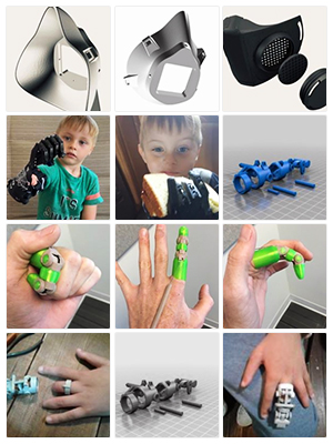
SHARKCAD CAN HELP YOU DESIGN PROJECTS SUCH AS:
|
 |
COMPATIBILITY AND FILE SHARING
We want to be the best CAD software and we believe that should include the flexibility to work with a variety of other software programs and file types as needed.
- SharkCAD provides compatibility with AutoCAD® DWG files
- DXF/DWG versions from R12 to 2019
- STL Import/Export for 3D printing
- SVG Import and Export
- 3MF Import & Export
- VMRL 2.0 Texture Support
- OBJ Texture Support
- Adobe Illustrator® Import
- PDF Import
- SketchUp 2019 Import/Export
- Collada™ (DAE) Import/Export
SINK YOUR TEETH INTO SOME OF SHARKCAD’S KEY FEATURES
Welcome to the world of Jump into the exciting world of 3D mesh modeling, coupled with 2D drafting tools, and you’ll be hooked. Some of the features that make SharkCAD the best choice for professional CAD design:
- Design complex organic shapes with extensive NURB surface modeling tools
- 2D Geometric and Dimensional Constraints to manage geometrical relationships between 2D shapes

- Push/Pull Modeling allows 3D surfaces to be edited with your mouse and cursor
- Powerful 3D editing tools such as blending, chamfering, and shelling

- Architectural and woodworking tools such as rabbet, miter and dovetail joints
- Extensive 2D drafting tools such as text, dimensions, 3D to 2D drawing, bill of materials
- Multiple Viewports provide 2, 3 even 4 views of your design and drawing between them
- Integrated Photo Realistic Rendering and support for Keyshot LiveLinking™
- And much more!

INTUITIVE DESIGN AND EDITING UTILITIES
Drawing precisely is easy with SharkCAD! We have designed it to be user friendly and intuitive to work with.
The LogiCursor™ anticipates your next action and guides your cursor to potential point selections in the drawing.
The Gripper adds drag and drop capabilities to make editing designs easy breezy.
Customizable Grids add another level of ease by providing precision drag and drop in rectangular, polar (circular), and isometric layouts.
PRECISION DRAFTING AND ANNOTATIONS
SharkCAD is also a robust design documentation tool with over 20 customizable dimension styles, including industry dimension formats.
Other great features to help you document and annotate your projects include:
- 26-dimension styles
- Import bitmaps for logos and reference images
- Spell check is provided for another level of accuracy
- Single click Fills and Hatch
ARCHITECTURAL PLANNING TOOLS
SharkCAD includes all the professional level architectural tools you and your team need to draft, print, and collaborate on projects together.
- Architectural wall tools
- Composite walls to show materials
- Parametric doors and windows
- Instant 3D walls, roofs, and floor slabs
- Compatibility with AutoCAD® DWG files
- ACIS®-based geometry means you are creating with the same technology as software that costs thousands of dollars
WOODWORKING TOOLS
SharkCAD includes tools to speed up your woodworking projects. You can quickly create otherwise tedious joints such as Dado joints and miter joints.
- Joints including rabbet, miter, and dovetails
- Dado joints including options for through, stopped or blind
- Edge treatments including cove, round, bullnose, Dupont, waterfall, Ogee, and custom
- Tongue & Groove
3D MODELING TOOLS
SharkCAD provides powerful solid modeling technology found in many higher-end products. Additionally, SharkCAD delivers surface modeling tools to expand design capabilities.
- Feature-based History Tree for editing
- A complete design tool with extrusions, Booleans, surface modeling for more complex smooth surfaces
- Precise geometry suitable for 'concept to manufacturing'
- Associative surface modeling
3D PRINTING TOOLS
SharkCAD includes 3D printing tools to prepare and validate your designs to make them 3D printer ready.
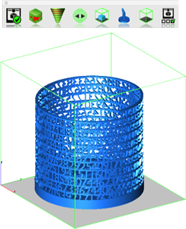
3D PRINT CHECK
Checks for print viability, displaying warnings or errors to the user.
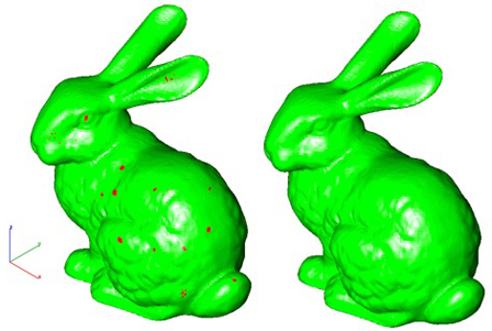
SURFACE NORMALS CHECK
Facet normals define the inside and outside areas of a part. If facet normals are pointing the wrong way, the 3D printer may have problems creating the part. This will check for problems and we have several commands that can help you fix it.
OVERHANG ANALYSIS
This will help you visually inspect modeling areas that may require structural support for 3D printing. Meshes, surfaces, and solids facets normals are compared to the work plane direction. Angles that are less or equal to 45 degrees are highlighted as red.
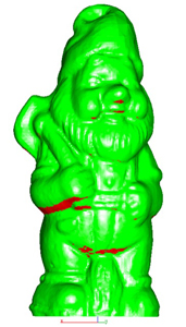
WALL THICKNESS ANALYSIS
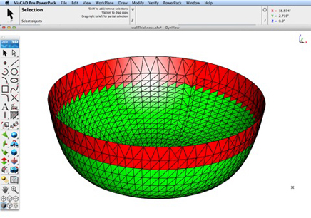
This tool provides a means to visually inspect modeling areas that may be too thin for 3D printing. Meshes, surfaces, and solids facets are examined using ray intersections.
PREVIEW SLICES
This interface will help you to slice models given a direction and thickness. The dialog box allows for animation through the slices and single-stepping. Use to verify that a part has closed, non-overlapping sections, a requirement for 3D printing.

AUTO POSITION
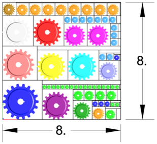
The Auto Position tool translates the model to the positive x, y coordinate system at z=0.
SUPPORT STRUCTURE
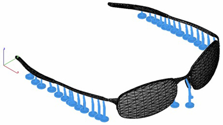
Manually adds geometry to support material as it is created by the 3D printer. Support structures controls, include Attach Radius, Midpoint Radius, Base Radius, Base Thickness, and Drag base and midpoints to modify structure location.
SHOW PRINTER VOLUME
Toggles the boundary of the default 3D Printer. The volume is defined within the Printer Definitions dialog box.
PRINTER DEFINITIONS
Sets key parameters of the 3D printer, including length, width, and height of the volume accessible by the printer. The parameters in the Printer Definitions dialog box are used for commands such as 3D Print Check and Auto Position.
POWERPACK NOW INCLUDED!
SharkCAD v14 is packed to the gills with new features. We took our popular PowerPack add-on and baked it into our version 14 release at no additional cost to you. That adds a collection of over 70 new tools including 3D printing repair tools, new modeling tools and general utilities that will increase productivity and make your existing and future designs 3D Printer ready.
Read about some of our most exciting new features below.
UNFOLD SHEET TOOL
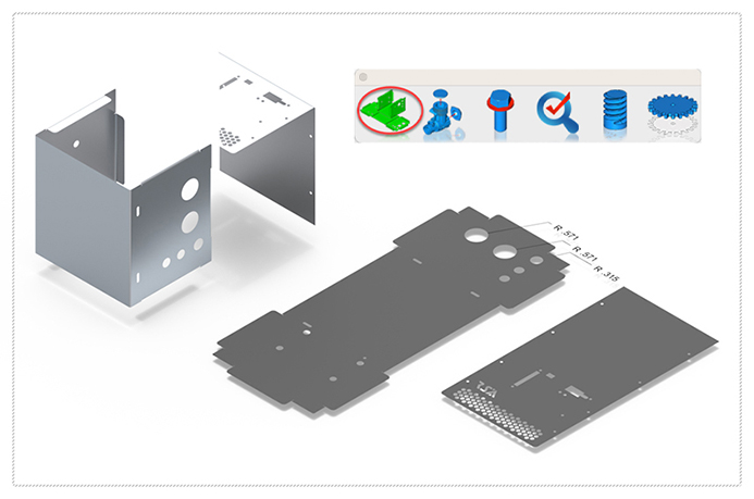
The Unfold sheet tool is used to flatten analytical or NURB surfaces into the xy plane. The unfold operation works on a sheet body that is flattened by mapping it onto a plane. The output body is a B-rep body consisting of planar faces and edges.
If the input sheet body is stretched and/or compressed during the unfolding, the shapes of features on the input body will be transferred faithfully to the output body, at the cost of some area distortion. The amount of distortion depends on the curvature of the input sheet body, as well as the constraints imposed by how faces are connected. Developable Surfaces (with zero Gaussian curvature), such as cylinders and cones can be unfolded without any area distortion. Other curved surfaces (with non-zero Gaussian curvature) may have some distortion during unfolding.
The unfold tool is in the mechanical tool palette located under Tools in the menu bar. Selecting the tool icon prompts the user for the surface or body to unfold. The surface to unfold fold must have zero thickness such as with a surface or mesh object. For example, it does not accept a solid. Select any surface in the body and the results are displayed in the XY plane at z = 0.
BOM FRACTION MEASUREMENTS
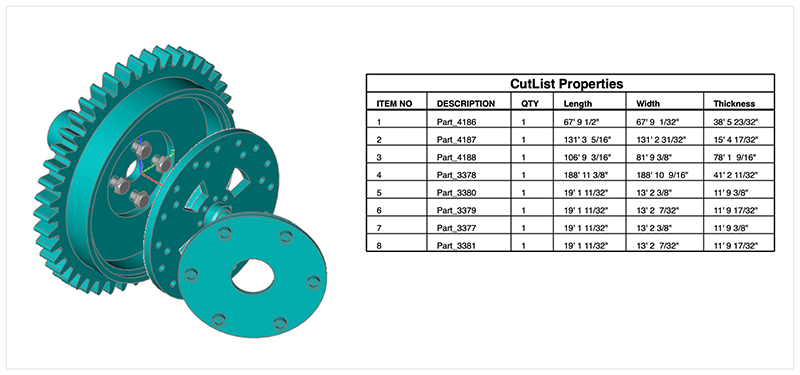
The Bill of Material Create BOM feature has a new option to support fraction measurements. To use this feature, select the Attributes and BOM dialog box from the Tools menu. Select your objects and associated a data set such as CutList properties. Apply to selected. Now select the Create BOM option to create a table. In the BOM Settings dialog box, select the Decimals pull down option. And then Select Fractions to display measurements as factions of feet and inches.
CLASH DETECTION
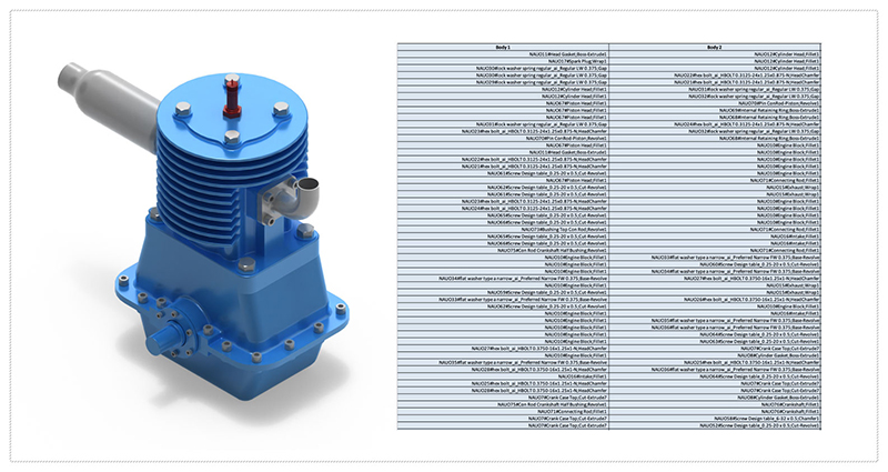
A ‘clash’ is the result of two objects in your design taking up the same space. A clash detection is the technique of identifying if, where, or how two or more parts of a grouping interfere with one another. Clash Analysis is suitable for checking mate, align, and interference checks for parts and assemblies. Example types of interference may be:
- volume sharing
- face sharing
- edge sharing
- vertex sharing
The Clash Detection tool will report up twenty different types of clashes.
COMPARE PARTS
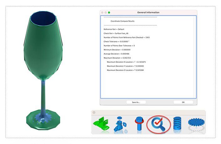
The Compare Parts tool examines two parts for deviations in geometry. Deviations are shown as minimum distance vectors between the two parts.
The first part selected must be a surface or solid. The second part must be a mesh which can be an imported object such as a STL, OBJ, or point cloud via the PLY file format. The result of the tool is provided as a report plus distant deviations represented by line entities between the two parts.
-
Number of Devices/Users1 Device
-
License Type
-
Product Family
-
Delivery Method
-
PlatformWindows
-
Compatible Operating SystemsWindows 7, Windows 8, Windows 10, Windows 11
-
Technical Support
-
Region RestrictionsCan only be used in the United States and Canada
We offer a 30 day Refund Policy if the following requirements ARE met:
1. The Software has not been downloaded. (This is verifiable by us)
2. The License Key has not been entered by you. (This is verifiable by us)
3. The Order is not greater then 30 days old.
In the rare case there is an error on our part including our advertising, order process, etc, this will also qualify for a refund.
Refunds can be requested by logging into your account here.
If the above requirements ARE NOT met:
That sale is considered final and cannot be refunded.
It cannot be refunded because the Software has been used by you and cannot be used again by anyone else nor can it be revoked.
This is standard refund procedure for Software no matter where you purchase it.
Payment & Security
We Accept
Your payment information is processed securely. We do not store credit card details nor have access to your credit card information.


